Uses
- Air heaters
- Boilers
- Chemical stills
- Heat exchangers
- Ovens
- Draft furnaces
- Dryers
- Kilns
Operation
Standard Atmospheric Torches use draft to induce combustion air into the systems. This draft air is independent of gas flow and is constant at all input rates. With reduced gas flow the mixture quality usually becomes leaner and approaches unstable ratios, limiting turndown capacity to less than 2 to 1 on the standard torch.

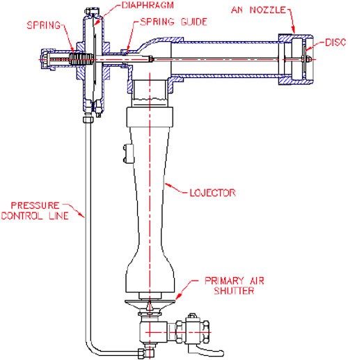
Hi-Lo Torches use a diaphragm and spring coupled by an operating rod to the port disc. With the modulating valve open, full gas pressure is applied to the diaphragm and gas orifice. The gas pressure force on the diaphragm overrides the spring force and moves the diaphragm assembly towards the nozzle. The operating rod moves the disc to an open position providing full nozzle capacity. The gas orifice size sets the maximum gas flow and the air shutter adjustments control the desired primary air flow.
On turndown both the gas flow through the orifice and the pressure on the diaphragm are reduced. Spring force retracts the nozzle disc closing the burner port area reducing induced draft flow in proportion to gas flow.
Air-Gas mixture ratios remain within stable limits at all input rates.
The spring guide effectively seals the draft from the operating diaphragm even with very high drafts of up to 6” W.C.
Control
The Hi-Lo Torch is designed for automatic control with a single gas flow control valve. Pneumatic, electric or direct actuator drives are coupled to proportioning valves. Recommended minimum travel time from high to low fire is 5 seconds. This time is necessary to coordinate the nozzle disc movement with the gas flow changes.
Capacity
Hi-Lo Torch capacities are limited by combustion air induced by operating draft and gas pressures at the orifice. Size selection should be based on both factors.
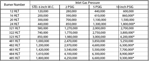
Table I lists the maximum capacities of Hi-Lo Torches at 0.1 inch W.C. draft and various gas pressures. Multipliers for other drafts are listed in Table II.
Capacities shown in Table I and multipliers in Table II are based on maximum primary air shutter openings and 30% primary aeration on standard pressure gas and 50% on medium pressure gas.
Table I – Capacity: All Fuel Gases
BTU/HR @ 0.1 Inch W.C. Draft

* At these capacities additional secondary air openings are required.
Table II
Draft vs Capacity Multiplier

Hi-Lo Torch Initial Adjustment
- Open secondary air cage shutter full and primary air shutter 1/4″.
- Check pilot ame. This should be blue, stable and extend to main nozzle.
- Slowly open manual gas shut-o valve and verify main burner ignition.
- At high re (maximum input), set primary and secondary air shutters for desired ame. Opening primary air shortens flame. Flame color normally should be blue with red to orange tails.
- Throttle gas ow slowly and observe flame. Set low re stops on valve at minimum position.
- The actuator spring is factory set to begin closure at 2 inch W.C. on standard press. models and 1.5 PSIG on medium press. units. These settings normally do not require adjustment.
- On standard pressure models, if the flame flashes back beyond the burner or becomes unstable during the turndown test, close the primary air shutter slightly or reset the actuator spring (clockwise adjustment) for faster disc closure or both as required.
- Tighten lock screws on secondary air control cage and primary air shutter locknut.
Options And Dimensions

Dimension Table
Inches ± 1/8

* Dimensions shown for HLT-L model, for HLT-M add approximately 3/4” to dimensions.
Burner Selection Procedure
- Determine total HTU/HR input required.
- Divide total BTU/HR input by number of burners desired to obtain individual burner input.
- In Table I find capacity equal to desired BTU/HR input in column of available gas pressure and specify basic burner catalog number. Use multiplier Table II for drafts other than 0.1” W.C.
- If available gas pressure is 6” W.C. to 2 PSIG add suffix “L” to basic catalog number. If the gas pressure is 2 PSIG to 10 PSIG add suffix “M” to basic catalog number.
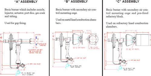
- Select burner assembly desired and add suffix “A,” “B” or “C.”
Example: 16HLT-LB Hi-Lo Torch Natural gas 6” W.C. 0.1” W.C. Draft (200,000 BTU/hr)


